High-voltage switch's dividing and closing speed, dividing and closing time, dividing and closing levels of different periods, and the operating voltage of closing and closing coils directly affect the closing and breaking performance of high-voltage switch. The high-voltage switch can only ensure the proper breaking and closing speed to fully exert its ability to open and cut the current, as well as to reduce the electrical wear of the contacts caused by the pre-breakdown during the closing process and to avoid the burning of the contacts and the fuel injection, and even explosion occurs. However, if the closing speed is reduced, if it is closed to a short-circuit fault, it will cause the contact to vibrate or cause it to stand in a stagnation state due to the obstruction of the contact of the contact with the electromotive force, which is also likely to cause an explosion, especially in the case of automatic reclosing. This is especially true in a successful situation. Conversely, if the speed is too high, the moving mechanism will be subjected to excessive mechanical stress, resulting in damage to individual components or shortened service life. At the same time, due to strong mechanical shock and vibration, the contact bounce time will also be lengthened. The vacuum is similar to the SF6 high voltage switch.
High-voltage switch points and closings at different periods will result in the incomplete phase access or disconnection of the line or transformer, which may result in overvoltages that are detrimental to the insulation.
Some aspects of the mechanical characteristics of the high voltage switch are characterized by the contact action time and the movement speed as the characteristic parameters. In the mechanical characteristic test, the most important are the rigid velocity, the rigid closing velocity, the maximum opening velocity, and the opening time. , Closing time, closing time, splitting-closing time, and the same period of time.
First, the definition of part of the time parameters
1. Opening time
It refers to the time interval from the start moment of the high voltage switch opening operation (the instant when the opening command is received) to the instant when the contacts of all poles are separated. It should have a short opening time to reduce the arc energy at the time of opening and prevent the arc from welding the contacts.
2. Closing time
Refers to the high-voltage switch in the sub-position, from the time when the closing circuit is energized until all pole contacts are in contact. The closing time must be within the specified time range. If the closing time is too short, the DC component will be too large when the system is short-circuited, which may cause difficulty in closing. If the closing time is too long, the stability of the system will be affected.
3. Sub-combination time
It is the time interval from the moment of separation of all pole contacts to the moment of first contact pole contact when the high voltage switch is reclosing automatically.
4. Co-minute time
It is the time interval from the contact contact of the first contact pole to the moment of separation of all polar contacts in the subsequent sub-operation when the high-voltage switch is in the process of splitting the unsuccessful reclosing or splitting operation separately.
5. Concurrency of opening and closing operations
It refers to the time difference between three-phase breaking and contact moments when the high-voltage switch is opened and closed, and the time difference between the moments of breaking and contacting of the in-phase arc extinguishing unit contacts. The former is called phase synchronization and the latter is called in-phase fracture. Between the same period.
Second, the measurement of high-voltage switching time parameters
In the field test of the high voltage switch, the opening time, closing time, and the closing and closing synchronization measurement should generally be performed. For the high voltage switch with the recloser operation, the split-combination time and the closing time should also be measured.
1. Using a stopwatch to measure time
The electric stopwatch has the advantages of simple measurement and convenient use. However, the electronic stopwatch is difficult to accurately measure the phase difference between phases or between fractures, so it has gradually been replaced.
2. Light oscilloscope measurement time
The use of a ray oscilloscope can measure the switching and closing time of the high-voltage switch, the synchronism difference, and the action of the closing and closing electromagnets. This method has the advantages of accurate and intuitive measurement, and the ability to simultaneously measure multiple time parameters.
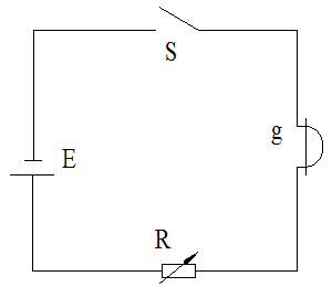
(1) The basic principle of measurement. The wiring principle is shown in Figure 1-1. The test circuit of the optical oscilloscope consists of the power supply E, the switch S, the adjustable resistor R, and the oscilloscope vibrator g circuit.
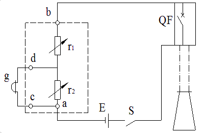
(2) Single-phase single-break high-voltage switch time measurement, the measurement wiring as shown in Figure 1-2.
Figure 1-1 Wiring of oscilloscope oscillator circuit
Figure 1-2 Wiring measurement principle with light oscilloscope
Before the measurement, the resistors r1 and r2 in the resistor box are adjusted to appropriate values. When the circuit is turned on, the current value in the circuit should be within the allowable range of the oscilloscope.
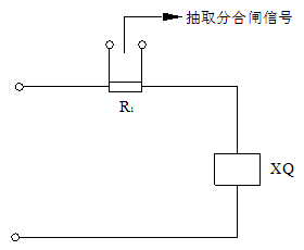
(3) Current signal. In the mechanical test of the high voltage switch, the current waveform of the opening and closing electromagnets when operating the high voltage switch is usually called the current signal. It is the sign that the high voltage switch accepts the opening and closing operation instruction, this sign is the indispensable signal in the high voltage switch time measurement, its measurement principle wiring is shown as in Fig. 1-3.
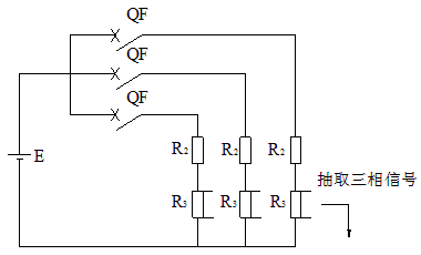
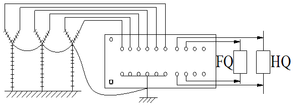
(4) Three-phase time measurement of high voltage switch. A high-voltage switch is generally composed of three phases, so three-phase time parameters must be measured in a mechanical test. Figure 1-4 shows the wiring diagram for a three-phase time measurement with a ray oscilloscope.
Figure 1-3 Schematic drawing of the current signals of the sub-switching and closing coils
Figure 1-4 Three-phase time measurement wiring diagram with a light oscilloscope
XQ-coils
Because the oscilloscope has a wide time scale range and high precision, and can intuitively reflect the changes of the relevant parameters of the high-voltage switch during the operation, it has been the main method for measuring the mechanical characteristics of the high-voltage switch in the past. With the development of electronic technology, there has been the use of computer technology to measure the parameters of the mechanical action of high-voltage switches, which has gradually replaced the use of optical oscilloscopes.
Third, the definition of speed parameters
1. Contact speed
Refers to the instantaneous speed of separation of the moving contact and the static contact during the opening and closing of the switch. When the technical conditions are not specified, the national standard recommends that the average speed within 0.01s be used as the instantaneous speed of the rigid point immediately after the point is divided, and the calculation point of the nominal overshoot is used as the just-minute calculation point.
2. Contact rigidity
Refers to the instantaneous speed of movement of the movable contact and the static contact when the switch is closed. When the technical conditions are not stipulated, the national standard generally recommends that the average speed within 0.01s before the rigid joint is taken as the instantaneous speed of the rigid joint, and the calculation point of the nominal overtravel is taken as the rigid joint calculation point.
3. The maximum opening speed
Refers to the maximum value of the average speed of the section in the process of opening and closing the switch, but the length of the section shall be in accordance with the technical conditions. If not specified, the calculation shall be made in 0.01s.
Fourth, the measurement of high-voltage switching speed parameters
The high speed switch's speed parameter is expressed by its split and close speed. Since the speed of the high-voltage switch at each moment during the movement is different, the general concern is the rigidity, rigidity and maximum speed. According to the above definition requirements, the following describes several ways to measure the motion characteristics of high-voltage switches.
1. Electromagnetic oscillator speed measurement method
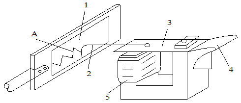
Electromagnetic Oscillator The principle of speed measurement is shown in Figure 1-5.
Figure 1-5 Electromagnetic Oscillator Speed ​​Measurement
1- Sports cardboard; 2-Vibrating pen; 3-Armature; 4-Vibrating piece;
5-coil; A-hard, rigid point
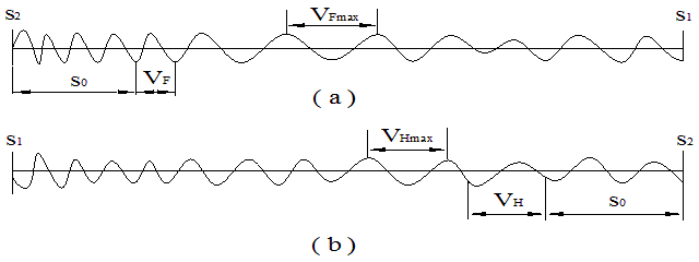
The sports board is connected to the movable contact via a speed measuring lever. When 50 Hz alternating current is applied to the oscillating electromagnet coil, the vibrating pen vibrates at a frequency of 100 times/s, and an oscillation waveform having a period of 0.01 s is drawn on the moving cardboard. The length of the waveform on the cardboard is the total stroke of the contact, and the corresponding number of cycles between strokes is the total movement time of the contact. During the movement of the contact, since the time interval between each adjacent peak is 0.01 s, the centimeter between the maximum peaks of the vibration curve is the maximum velocity value vmax of the contact. The determination of the position of the just-separated (combined) point is shown in Figure 6-8.
Figure 1-6 oscillator speed waveform
(a) Switching speed curve; (b) Closing speed curve
In the oscillating waveform diagram, first of all, it is necessary to clearly distinguish which of the two ends of the gate curve is the opening position S1, which end is the closing position S2, and then the closing position S2 is used as the starting point. The direction of the brake gate is equal to the length S0 equal to the over-travel value of the high-voltage switch. The end point of this line segment is the moment of the dynamic and static contacts. According to the national standard, the speed within 10ms after the contact is separated (before contact) is the speed of just dividing (combining), so what phase of the curve depends on the end of the end of the travel, and then one wavelength of the same phase is taken, which is the required Just divide the velocity vF or the rigid velocity vH.
2. Drum type, potentiometer type speedometer
Drum type speedometer is a stylus pen attached to the moving contact system. It reflects the movement of the drum along a curve drawn on a rotating drum rotating at a constant angular velocity. The potentiometer-type speedometer measures the operating condition of the high-voltage switch based on the voltage value reflected by different positions of its sliding contact on the resistance bar. These two measurement methods can intuitively determine whether the high-voltage switch contacts have any abnormal phenomena such as jamming and buffering during the entire movement, and can roughly measure the inherent points and closing time of the high-voltage switch, and the speed measurement accuracy is high. These two methods are relatively simple. The disadvantages are that they are relatively bulky and have a single function and have been rarely used.
V. High-voltage switch characteristic tester
With the wide application of computer technology, high-voltage switch characteristic testers have emerged. It can measure the time, speed and other parameters of the switch at the same time in the test process, which improves the working efficiency. This is the direction of the switch test.
1. Principle of photoelectric speed measurement
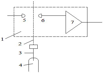
Due to the simple and reliable structure of photoelectric speed measurement, most switch characteristics testers use photoelectric sensors to switch speeds. Photoelectric testing is the use of counting (or timing) the detected light signal to measure the travel and speed of the contact. Figure 1-7 shows a schematic diagram of the structure of photoelectric speed measurement.
Figure 1-7 Photoelectric speed measurement structure
1-sensor head; 2-grating scale; 3-speed lever; 4-moving contact;
5-LED; 6-Photosensitive receiver; 7-Shaping circuit
In Fig. 1-7, a grating with a light hole is connected to the moving contact of the switch via a speed measuring rod. When the moving contact moves, the grating scale is moved up and down. The light emitted by the light emitting tube 5 can be irradiated onto the photosensitive receiving tube 6 through the light hole in the grating ruler, or blocked by the opaque portion of the grating ruler. The detected optical signal is converted into a corresponding square wave signal by shaping circuit 7 and sent to a high voltage switch tester for calculation and processing.
The following uses the GCKC-III high-voltage switch dynamic characteristics tester produced by Shanghai Guanjian as an example to illustrate the use of this type of instrument. In addition to the test data, the instrument can also give a detailed waveform diagram, and the switch stroke curve and the fracture waveform are plotted on the same graph, so that the conditions of each quantity and the mutual relationship between them can be intuitively understood. , Help analyze the status and working conditions of the switch, and promptly discover possible defects and hidden dangers.
2. Connection and wiring
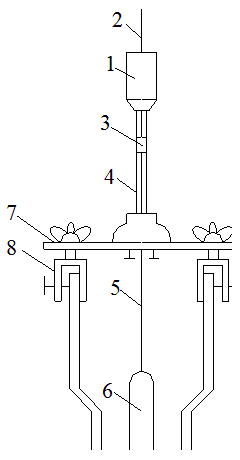
Figure 1-8 shows the wiring diagram for testing low oil high pressure switches using this type of instrument. Figure 1-9 shows the installation of the oil high-pressure switch speed sensor. The speed sensor is fixed on the upper part of the switch by the tubular bracket. The grating scale passes through the sensor and the well is connected with the moving contact of the switch through the speed measuring rod. The speed signal cable is plugged into the jack on the back of the instrument.
Figure 1-8 Schematic diagram of test wiring for less oil high voltage switch
FQ-opening coil; HQ- closing coil
Figure 1-9 Schematic diagram of the installation of a low oil switch with a low oil pressure sensor
1-sensor head; 2-light ruler;
3-light-foot joints; 4-tubular stents;
5-speed lever; 6-moving contact;
7-Insulator board; 8-Jig
After the connection is completed, the instrument is ready to go. Once the high-voltage switch is operated, the instrument will automatically determine whether the operation is split, merged, split or split, and test the relevant parameters. Technical display or print button, you can display data or print out.
3. Test of vacuum high voltage switch
The test method for the time characteristic of the vacuum high voltage switch is the same as other high voltage switches. For vacuum high voltage switches, it should be noted that the closing bounce time is not more than 2ms. If the closing bounce time is too long, it will aggravate the burning of the contacts and even result in the welding between the moving and the static contacts. The speed of vacuum high voltage switch is tested according to the average value of a certain stroke. Usually a special auxiliary contact is installed at the movable contact end of the vacuum high voltage switch, and it is used as the contact or separation of the movable contact of the vacuum high voltage switch. The start or end of the time.
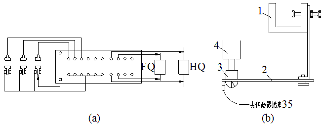
Figure 1-10(a) shows the principle wiring diagram for testing the mechanical characteristics of the vacuum high-voltage switch using this type of high-voltage switch tester. The arrows in the figure indicate the auxiliary contacts for speed measurement.
Figure 1-10 (b) shows the structure of the fixture used to install auxiliary contacts. Fixture 1 is used to fix it in a suitable position near the movable contact of the high voltage switch. When it is necessary to measure the closing characteristics, the auxiliary contact should be brought into contact with the movable contact on the movable contact side of the high voltage switch. The average closing speed thus measured is the average speed of all the closing strokes of the high voltage switch. When it is necessary to measure the opening characteristics, when the high voltage switch is in the closing position, the auxiliary contact should be placed 6mm away from the moving direction of the moving contact. The average speed of the sub-gate measured in this way is the average speed within 6mm.
Figure 1-10 Vacuum high voltage switch test
(a) Vacuum high voltage switch test wiring diagram; (b) Vacuum high voltage switch test schematic
FQ-opening coil; HQ- closing coil
1-Cages; 2-Insulating sheet; 3-Auxiliary contacts; 4-High-voltage switch contacts
4. Test of SF6 high voltage switch
Since the SF6 high-voltage switch interrupter cannot be opened, it is not possible to test the moving contact directly. Usually, the SF6 high-voltage switch mechanism is used for speed measurement. When the SF6 high-voltage switch is used for speed measurement, the sensor head can be fixed in place according to the specific structure of the high-voltage switch, and the grating scale can be connected to the moving part of the high-voltage switch in a certain way to achieve speed measurement. The speed measurement results should be Satisfy the requirements of the technical conditions of the high voltage switch.
ESD Pa6 Sheet
Product Details
ESD PA6 Sheet provided stable and uniform antistatic value. This materials is suitable for automatic lathe machining, especially suitable for the manufacture of precision parts.
|
Product
|
Thickness(mm)
|
Size(mm)
|
Color
|
Density(g/cm³)
|
|
ESD PA6 SHEET
|
8-100
|
610*1220
|
Black
|
1.2
|
Advantages:
