Oil pipelines are extremely important transmission equipment in the modern energy industry. The requirement for accurate measurement of fluids in oil pipelines is a goal pursued by relevant technicians, and it is also a technical problem that never ends. After all, industrial production is for technology. The pursuit is endless. With the rapid progress of science and technology, this problem has also been solved more and more. In view of this situation, through the work of this unit, the author communicates the design issues of the turbine flow meter in the oil pipeline. Home Spin Bike,Indoor Spin Bike,Commercial Spin Bikes,Spinning Exercise Bike ZHEJIANG POWERTECH CO,.LTD , https://www.chinatattoo-supplies.com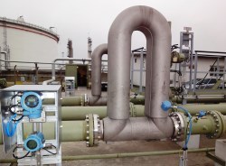
First, the working principle of turbine flowmeter
   Turbine flowmeters work by installing a turbine in the pipeline, supported on both sides by bearings. As the fluid passes through the pipeline, it impacts the blades of the turbine, and the impact force generates a driving torque to the turbine so that the turbine rotates against the friction torque. In a certain flow range, for a certain fluid medium viscosity, the rotational angular speed of the turbine is proportional to the fluid flow rate. Thus, the fluid flow rate can be obtained by the rotational angular velocity of the turbine, whereby the fluid flow through the conduit can be calculated.
The rotational speed of the turbine is detected by a sensing coil mounted outside the housing. When the turbine blade cuts the lines of magnetic force generated by the permanent magnets in the casing, it causes a change in the magnetic flux in the sensing coil. The sensing coil sends the detected magnetic flux cycle change signal to the preamplifier, amplifies and reshapes the signal, generates a pulse signal proportional to the flow velocity, and sends it to the unit conversion and flow totalizer circuit to obtain and display the cumulative flow value; At the same time, the pulse signal is also sent to the frequency current conversion circuit, and the pulse signal is converted into an analog current amount, which in turn indicates the instantaneous flow rate value.
  
Second, the turbine flow meter design and application in the oil pipeline
1. The main performance of turbine flow meter
Rated pressure: 4 MPa; Length: 600 mm; Flow range: 50 to 250 cubic meters per hour; Pressure drop: Pressure loss less than 40 kPa at maximum flow (Water as test medium When); total mass: less than 40 kg. It can work in the environment from minus 41 degrees Celsius to minus 46 degrees Celsius. The meter shows both instantaneous and cumulative flow, and can display the total cumulative flow, batch cumulant, instantaneous flow, and medium temperature. The reading is convenient, clear and intuitive.
The communication interface is equipped with a transmission distance of not less than 900 meters. The meter coefficient applies multi-stage non-linear correction. According to the meter coefficients corresponding to different flow points, the meter coefficient of the flow meter is calculated by interpolation. Temperature compensation function: The reference temperature is 20 degrees Celsius, different oils are compensated by different temperature volume coefficients.
Measurement accuracy: zero secondary.
September 24, 2021